
|
|
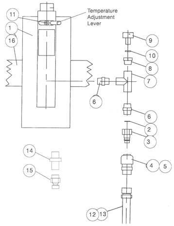
Item |
Part No |
Description |
|||
|
16 |
NWV12 | WAIST BELT | ||||
|
15 |
CPF0008 | 3/8 COUPLER PLUG | ||||
|
14 |
A8 | 3/8 ADAPTER NIPPLE | ||||
|
13 |
HOSE 34S 20 | 10MM OF BREATHING AIR SUPPLY (X20M) | ||||
|
12 |
HOSE 34S 10 | 10MM OF BREATHING AIR SUPPLY (X10M) | ||||
|
11 |
FASM635A | SCREW | ||||
|
10 |
MSV7 | ‘O’ RING | ||||
|
9 |
APH10556 | INDIACATOR GAUGE | ||||
|
8 |
APH10559 | ADAPTOR BUSH | ||||
|
7 |
RCAMV10 | FEMALE TEE | ||||
|
6 |
NWV23 | ¼ ADAPTOR NIPPLE | ||||
|
5 |
CPF004C | QUICK DISCONNECT COUPLING FOR 10MM HOSE | ||||
|
4 |
CPF004A | QUICK DISCONNECT COUPLING FOR 6MM HOSE | ||||
|
3 |
APH8849 | QUICK DISCONNECT NIPPLE | ||||
|
2 |
APH8448 | FILTER SCREEN | ||||
|
1 |
APH 4378 | SHIELD | ||||
|
Length of air supply hose |
Internal dia of hose |
Supply pressure |
Air Flow |
|||
|
20m |
6mm |
3.4 |
170 |
|||
|
60m |
10mm |
5.2 |
170 |
|||
Warning: The intrinsic noise level generated by the relatively high air speed through the Climate Control Tube may exceed 80dB(A). Therefore ear defenders (ED1) or ear plugs (EP1) MUST BE WORN
INTRODUCTION
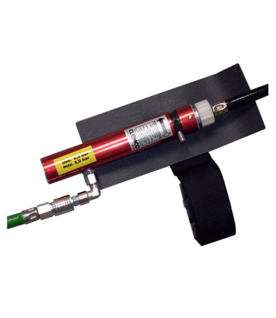
1.1 The Clemco climate control tube has been specifically designed for blast cleaning operative protection and comfort and satisfies the requirement of EN271 when used with a Clemco approved blasting helmet
The above approval applies only when the respirator system is used complete without modification, change or substitution
1.2 The unit supplies the user with either warm or cool breathing air. The temperature adjustment lever on the unit allows the user to adjust the temperature of air to the blasting helmet to suit the individual requirements. (Approx. 10°C to 30°C)
AIR SUPPLY
- The Climate control tube must be supplied with adequate volume of respirable breathing air to ensure minimum supply of 170ltrs/min into the helmet. Under normal conditions the lengths of breathing air supply hose must not exceed 20m (6mm i.d.) or 60m (10mm i.d.) see table 2. In extreme temperature conditions the maximum range of air supply temperature adjustment can only be achieved using 10mm i.d breathing air supply hose
- The air compressor should be equipped with a high temperature or carbon monoxide (C0) warning device or both. An overloaded compressor or one in poor mechanical condition may produce carbon monoxide (CO) and objectionable odours.
- When using portable compressors, precautions must also be taken to prevent exhaust gases from entering the air intake. It is advisable to have the exhaust gases ducted downwind to a safe non combustible area
- A breathing air filter should be installed between the air fed helmet. This should remove objectionable odours, pipe scale, condensed moisture, oil mist, oil vapours and any other particulate matter
- Checks should be carried out prior to use and at suitable intervals to ensure that the volume and quality of breathing air meets legislated Health & Safety requirements
Warning: To comply with health and safety requirements the breathing air must be tested frequently for the presence of contaminants i.e. Carbon Monoxide (CO) Hydrocarbons, etc. Kits are available for this purpose
OPERATING INSTRUCTIONS
These operating instructions should be used in conjunction with those issued with the approved air fed blasting helmet
Warning: The maximum recommended inlet air pressure for the unit is 110 p.s.i. Under no circumstances must it be connected to an air supply greater than 110 p.s.i. (75 bar)
3.1 Turn OFF the air supply to the system then remove existing air control valve and replace with the climate control tube
3.2 Attach the quick disconnect coupling of the air supply hose to the Climate control tube as shown
3.3 Move the temperature adjustment lever to warm (min flow)
3.4 Turn ON the air supply and regulate the air pressure until:the air flow meter
(when fitted) reads 170 ltr/min or the indicator gauge (9) reads mid scale
3.5 Don suitable ear protection
- After placing the helmet over the head secure the waist belt over the cape and around the waist.
- To adjust the air temperature, move the adjustment lever at the top of the unit in the appropriate direction. Allow at least one minute for the temperature change to occur, the readjust if required
- Frequent monitoring of airflow may be carried out by consulting the pressure indicator (9) which should read clear of the red sector
MAINTENANCE
4.1 The climate control tube is a complex assembly and should not be disassembled any further than as instructed below
4.2 Disconnect the air supply
4.3 Unscrew the quick disconnected nipple (3) from the units air inlet
4.4 Remove the filter screen (2) using a small screwdriver and check it’s cleanliness
4.5 Clean the filter screen if necessary by blowing clean with compressed air
4.6 Reassemble the unit
4.7 The shield which protects the operator’s hip from any frosting which may form on the unit during operation should be replaced when worn
4.8 Replace the indicator gauge (9) and ‘O’ ring (10) if damaged or worn
Problem Solving
The climate control tube has no moving internal parts and requires minimal maintenance. Should inadequate air flow through the tube or a poor performance be experienced check :-
5.1.1 The indicator gauge (9) reads within the green sector
5.1.2 The filter screen (2) is free of obstructions ( See section 3)
NB The air discharge temperature is affected by the temperature and volume of the air supplied to the climate control tube